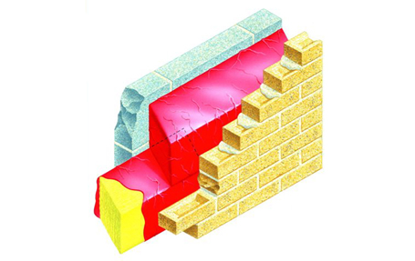
Timer Frame construction is one form of construction that calls for the exterior wall cavity to be compartmented. This is a straightforward procedure, and involves the use of sleeved non-combustible insulation located to fully fill the cavity width without interruption at heights that coincide with the floor levels around the building. In the event of a fire, the insulation sleeves prevent fire progressing via the cavity from one floor to the next.
Vertical barriers are also necessary to provide the same function. Thus every dwelling or living unit is effectively ‘framed’ within its exterior cavity wall, so if fire originates in one dwelling unit it cannot reach its neighbour via the cavity.
Such devices can address the requirement to provide cavity fire integrity and acoustic measures, but their very presence throws up a new problem. With the cavity fully bridged, what happens to rain that penetrates the exterior skin and gravitates to the level of the cavity barrier?
The insulation sleeves that started-off rectangular are intended to end up slightly compressed. This compression coupled with pushing the rectangular barriers down to locate them in the cavity results in the top of the rectangle becoming ‘hollowed’. Penetrating water can pool and reservoir on top of the barrier, sandwiched between outer skin and inner timber skin.
How does one prevent this happening? One method is to incorporate a dpc over the barrier, so shaped to direct water away from the inner skin. The dpc will require support at a higher level to hold it in place. There are also sleeved barriers where a surplus of sleeving on one or more sides can be used to act as a dpc. But is there a complication when forming long runs incorporating either of these methods?
For cavity barriers and stops to provide the requisite fire integrity around the building, they need to be continuous. To provide this continuity, individual lengths need to lap each other.
Lapping methods commonly involve the end of one barrier rising to lap with the other barrier that lowers. Easily done – until you consider the dpc requirement. How do you maintain dpc integrity when the end of a barrier lowers? How is arrested water prevented from discharging if each dpc arrangement does not have a stopend? Whether the dpc is separately introduced or is part of the sleeve, ensuring uninterrupted integrity can be exceedingly difficult to actually achieve. In the past few years, we have witnessed many distorted barrier installations, with questionable laps and questionable continuity. Interestingly we have not come across one instance of cavity barriers with some form of stopend to prevent discharge via a lap or an end.
So what is the purpose of this observation?
What has become apparent is that cavity barriers and stops are being incorporated with a total absence of dpc protection – but there appear to be no problems.
Similarly, cavity barriers and stops are being incorporated with leaking dpc arrangements, inconsistent dpc arrangements and discontinuous dpc arrangements. But again there appear to be no problems. But appearances can be deceptive.
When water pools or reservoirs (on top of or in and around a cavity barrier), damp penetration into the timber frame is prevented by the timber frame membrane. The membrane physically stops the water from soaking into the timber. Currently there appear to be no damp ingress problems and there will be none – as long as the membrane is guaranteed to perform in such a capacity for the life of the building – sixty years minimum? Our recent searches have not revealed a membrane able to guarantee this. Indeed, most manufacturers appear to qualify a limited membrane life when directly exposed to elements. And even the most robust of membranes is reliant on joins – will these last if water pools against them throughout the buildings life?
Whether many housing associations and flat owners have timber frame constructed units wherein the possibility of eventual decay of the timber frame might be dependent on a membrane not designed for such purposes is unknown.
The alternative barrier offered by Cavity Trays Ltd differs from ordinary barriers as it is shaped. The sloping top ensures water is always thrown forward – away from the inner skin.
The sloping bottom permits adjoining lengths to be lapped – and in lapping the fire integrity, the acoustic integrity and the dpc integrity is continuous and uninterrupted. No other barrier provides all these advantages.
Called the Cavi 60 Type SAF (pronounced ‘safe’) Cavi 60 denotes 60 minutes fire integrity rating and SAF stands for Sloping + Acoustic + Fire. An optional hard-cap dpc accompanies the Type SAF upon request.
The use of Type SAF sloping cavity barriers promotes a consistent and functionally compliant build detail and can reduce risk.
Cavity Trays
View company profile| T | (01935) 474769 |
|---|---|
| F | (01935) 428223 |
| E | sales@cavitytrays.co.uk |
| W | Visit Cavity Trays's website |
| New Administration Centre, Yeovil, Somerset, BA22 8HU |